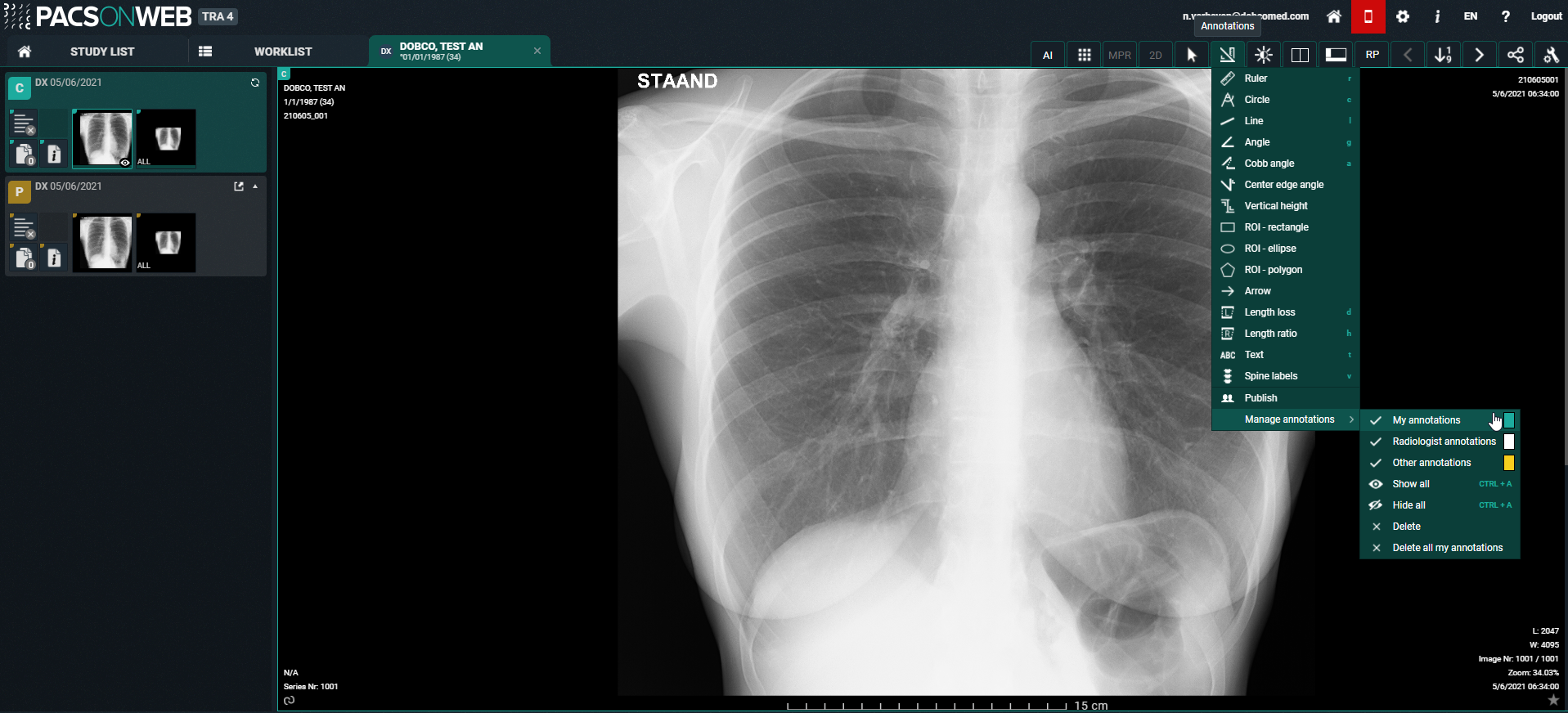
Annotations
Clicking Annotations displays a secondary menu, where you can perform a variety of measurements.
Icon | Measurement | Description | ||||
|---|---|---|---|---|---|---|
 | Ruler | Length measurement: measurement between two points.
| ||||
 | Circle | Circle with midpoint identifier and measurement of the radius. | ||||
 | Line | The line between two points.
| ||||
 | Angle | Three-point angle measurement: the angle defined by selecting three dots. | ||||
 | Cobb angle | The angle, defined by drawing two lines. | ||||
 | Center edge angle | Centre edge angle with angle measurement: Centre edge angle that creates an angle with the tangent of the figure on which it is placed. | ||||
 | Vertical height | The perpendicular line between 2 points. | ||||
 | ROI-rectangle | Density measurement for a rectangular area. Displayed values are: A: total area; Dens: average value for the area; Min: minimum value within the area; Max: maximum value within the area;  : standard deviation. : standard deviation. | ||||
 | ROI-ellipse | Density measurement for a elliptical area. Displayed values are: A: total area; Dens: average value for the area; Min: minimum value within the area; Max: maximum value within the area; : standard deviation. | ||||
 | ROI-polygon | Density measurement for a freehand annotation. Displayed values are: A: total area; Dens: average value for the area; Min: minimum value within the area; Max: maximum value within the area; : standard deviation. | ||||
 | Arrow | Arrow with text box to add text. | ||||
 | Length loss | Measure the difference in length between 2 lines. | ||||
 | Length ratio | Measure the length ratio of 2 lines. | ||||
 | Text | Text that can be added as an annotation to images. | ||||
 | Spine labels | Placing of the spine labels on the vertebrae.
| ||||
 | Publish | Make your annotations visible for all users that have access to the study. | ||||
 | Manage annotations | Manage the annotations, displayed on the image. | ||||
 | My annotations | Select if your personal annotations, marked in green, are displayed or not. | ||||
 | Radiologist annotations | Select if the annotations made and published by the creator of the report or received through DICOM, marked in white, are displayed or not. | ||||
 | Other annotations | Select if annotations made and published by other users, marked in yellow, are displayed or not. | ||||
 | Show all | Show all of the above annotations. | ||||
 | Hide all | Hide all of the above annotations. | ||||
 | Delete | Delete the annotation you have selected. (only for own annotations) | ||||
| Delete all | Delete all of your own annotations. | ||||

Note | |
 | Administrators Administrators of a radiology service can delete annotations by selecting the annotation and clicking the Delete button. |
Shortcuts
Tip | |
 | You can use the following shortcuts: |
Length measurement | R + left mouse button down |
Circle | C + left mouse button down |
Line | L + left mouse button down |
Angle measurement | G + left mouse button down |
Cobb angle measurement | A + left mouse button down |
Text | T + left mouse button down |
Spine labels | V + left mouse button down |
ROI ellipse | E + left mouse button down |
Length Loss | D + left mouse button down |
Length Ratio | H + left mouse button down |
Show all annotations | CTRL + A (keyboard) |
Hide all annotations | CTRL + A (keyboard) |
Delete Annotation | Select annotation + 'Delete' button |
Touch events on mobile devices
Independent of the selected image control or image editing tool, it is possible to drag or zoom in/out on the image:
• Zoom: pinch in or out on an image to zoom in or zoom out
• Pan: Hold two fingers on the image and move them simultaneously to drag the image
All image control and image editing tools can be used when set to active by touching the screen with one finger. E.g.: Use the scroll tool by sliding one finger up and down the image
Restriction | |
 | Please note: the following features cannot be used on devices running iOS12: • Region Zoom • Stepless Zoom • Zoom out You can use pinching in/out instead, as described above. • Pan • Density measurement • Spatial locator • Window level You can use presets. • Adding and modifying annotations |
Accuracy of measurement
Caution | |
 | The DeepUnity PACSonWEB measuring functions contain length measurements, angle measurements and density measurements based on the information that is provided by the original modality. • Length measurements are expressed in millimeters (mm). • Angle measurements are expressed in degrees (°). • Density measurements are expressed in the unit, as provided by the modality: Hounsfield Unit (HU), Optical Density (OD) or UnSpecified (US). • For measurement precision within the DeepUnity PACSonWEB environment, DeepUnity PACSonWEB relies on the precision of the information that is provided by this modality. In case a measurements displays "N/A" as the resulting value, it implies that the original DICOM images do not contain the required information to perform a quantitative measurement. |
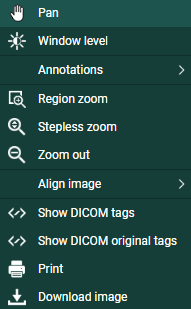
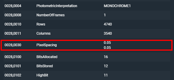
The accuracy of the modality is defined by the PixelSpacing, which can be verified by right-clicking on the related image and selecting Show DICOM tags.
PixelSpacing
The resolution (x,y) is available in the DICOM Tag PixelSpacing (0028,0030) and is expressed in mm.
The resulting value for a measurement within DeepUnity PACSonWEB, will always be displayed with two decimals as a result of the calculations, performed on the data provided by the modality.
A maximal deviance on a performed measurement of  must however be taken into account.
must however be taken into account.The accuracy of the different measurements have been validated for length measurements up to 0,01 mm and up to 1° for angle measurements.
If a measurement is made in another CE class IIa approved DICOM viewer for comparison, it must be taken into account that the measurement accuracy is affected by the coordinates of the start and end point of the line. DeepUnity PACSonWEB only allows measurement points to be set on pixel crossings. In case the DICOM viewer, used for comparison, allows any point to be selected to perform a measurement, again, a maximal deviance of can occur.
can occur.Besides the measurement accuracy, we take a rounding factor into account of maximum 0,05 mm for comparison of both resulting values since it cannot be guaranteed that the user who performs the measurement selects exactly the same pixels on the image in both viewers.
If a measurement is performed in an external PACS system and imported in DeepUnity PACSonWEB, the imported measurements can differ slightly when displayed in DeepUnity PACSonWEB. As the coordinates of the measurement points can deviate from the points, used in DeepUnity PACSonWEB, the resulting value will also deviate.